
“My personal favourite is the Magnetic Mates,” said David Falkingham, Solidworks manager for Northern Europe. “That for me is the highlight - just offering two components together and the system knowing how they should just fit. I’ve seen many a customer using Mates over the years and whilst I would say they’ve always been the best tool for doing assemblies in the industry, this makes it that much better. To see that Magnetic Mates is absolutely superb.”
Magnetic mates, which allows easy drag and drop mating in large, complex assemblies, is just one of the new features in Solidworks 17, the version released last month. However, it is probably the Interconnect feature that will cause most interest as it opens the door to collaborative working across multiple CAD environments. It allows users to open proprietary 3D CAD data directly into Solidworks, including data from Creo, CATIA, SolidEdge, NX and Inventor, while retaining associativity to the original file. It theoretically allows seamless working with anyone and will allow design changes to be incorporated much faster.
“It means we can sit in a mixed environment of CAD systems and then just use anybody’s data in our system,” said Falkingham. “I think that’s going to cause ripples through the industry. Previously you would need to do a data import, probably run something like Feature Works, which is fine if you want to do it the first time.But when the geometry then changes again in the originating system, you have to reimport it and some manual work to then change any of the designs that come off that.Now – it is seamless.”
Interconnect is currently undergoing final tests before it is released in Service pack two in the coming months. All other headline features of Solidworks 17 are available immediately in the new release. These include Visualise, Solidworks PCB and the PCB Connector.
The last two of these recognise the increasing interaction between electronics and mechanical engineers and were covered in the August issue of Eureka! Along with Visualise, a tool set for creating images, animations and interactive content, these packages were announced earlier in the year at Solidworks World.
Falkingham continued: “It is important now for us to demonstrate what we are doing for the future. Ten years back we just need to show what you’ve got now. The market has changed now and people want more of an understanding of what they’re going to be doing in three to five years’ time, not just in the next 12 months.Which is why you will see technology at SolidWorks World, that will then come out in subsequent releases.”
Other new features in the Solidworks 17 include new tools for Chamfer, Fillet, and Advanced Hole Specification. These create multiple variable chamfers in one operation; switch any pre-existing Chamfer to a Fillet and vice versa; capture and access previous hole definitions and apply pre-saved specifications; and construct stepped holes faster with one operation. To help create complex 3D geometry there are new surfacing features such as wrap, drag and drop, emboss, deboss, or 3D Curve.
Further emphasis is placed on simulation, particularly the instant display and implementation of simulation results, and also in the design process with enhanced communication through Solidworks MBD (model based definition) and control of design data in Solidworks PDM.
These features become particularly important for engineers with a global footprint. For example, Andrew Harlan, principal mechanical engineer, Myomo, commented: “We must fulfil a lot of medical device requirements, and SOLIDWORKS has been helpful for leveraging cutting-edge industrial design to get our work done faster and our myoelectric upper limb orthosis to market. The ability to collaborate with industrial designers, consultants and manufacturers across different time zones simplifies the whole process.”
Adding a dynamic edge
“FloEFD for Solid Edge is a leap forward for our customers who need to do flow analysis on their engineering projects,” said Dan Staples, vice president, Solid Edge product development, Siemens PLM Software. “This tool allows engineers to quickly run various 'what if’ scenarios and optimise their design directly inside of the Solid Edge window.” It is essentially offers the same functionality that FloEFD has offered other CAD packages, but until now CFD at this level has not been available within the Solid Edge. Now engineers can conduct analysis without having to leave the Solid Edge environment, removing the need for file transfers and translations, and therefore cutting the time (by an order of magnitude according to Mentor) involved doing CFD analysis. Nor is FLoEFD a ‘CFD-light’ solution. “We talk a lot in our positioning about trying to make it easier for people to use and more accessible to more engineers,” continued Watson. “So sometimes with that messaging, people make assumptions that it is a pared down type of CFD. But it has a lot of high-end functionality. You can do things like hypersonic flow, combustion, compressible flows, non-Newtonian flows, so it is a fairly powerful CFD tool but our focus still nonetheless is on ease of use, on having mechanical engineers, design engineers, be able to do some CFD.” FloEFD is available as an add-in to ST9, the latest version of Solid Edge. |
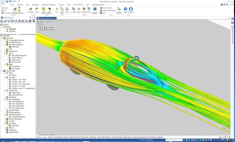 Mentor Graphics has worked with Siemens PLM to provide a fully embedded CFD solution, FloEFD, for Solid Edge CAD. Chris Watson, technical manager for the FloEFD products at Mentor Graphics, observed: “Solid Edge has an FEA solution which is based on Femap, but until now they didn’t really have an embedded CFD solution.”


