
Long-term tests
Highly flexible cables can be volatile, often reaching their stress limits quickly and with little warning after operating for long periods of time. So, how can ‘service life’ be predictable in such tempestuous components?
Richard Habering, product manager for chainflex cables at igus, explains that the standard tests performed by various European testing agencies including the IEC (International Electrotechnical Commission) do not offer clarity as they just simulate the wear regardless of the location of the energy chain or the chain material. He says: “Only a long-term test can offer predictability.”
To this end, igus operates the largest test lab for energy chains and cables in the industry, taking up 2,750m2 of floor space. Here, cables undergo tests under continuous operation on 58 different rigs. Since the exact reproduction of real working conditions is crucial, numerous test axes are available with different travel distances, accelerations and environmental conditions.
Extreme temperatures
Likewise, igus tests its products in temperature conditions from -40 to 60°C using climatic test chambers. Unlike standard cold winding tests, in which cables are wound up on a mandrel and cooled to the test temperature conditions just once, here the cables and chains are put under appropriate test temperatures and realistic motion conditions. They must withstand millions of strokes to prove they will endure the expected bending stress in a real application. A product passes the test only when no jacket ruptures occur, proving they have the correct flexibility.
Cable jackets by igus are made from an oil-resistant PVC compound, which provides high abrasion resistance over a wide temperature range. This is unique, since common PVC compounds used for ‘chain-suitable’ cables don’t normally meet these requirements. Another benefit is that in moderate temperatures, it’s not necessary to rely on expensive jacket materials such as polyurethane or thermoplastic rubber.
 Bundle instead of layer
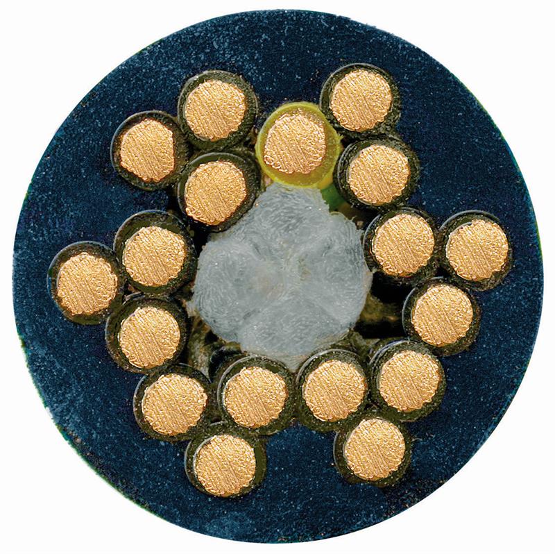
The findings obtained from the ongoing analysis of all tests over a period of 25 years has led to, among other things, the introduction of winding cores in bundles, similar to the concept used in steel cables.
In an elaborate bundle winding process, the cores are stranded in individual bundles with three, four or five wires; these are then wound with each other again into an overall bundle. The result is a cable that is both durable in motion and suitable for chains because, in contrast to a layered cable, each of the cores moves similarly in the inner and outer radius with the motion in the energy chain, thereby preventing relative stretching or compression.
In even more extreme movements, cables with a similarly complex structure are used. This ‘robot cable’ range is primarily used in industrial robots and must allow extreme movements, bends and torsion. Special damping elements give the cores the necessary freedom of movement in the cable interior. Also, because the more twisted the cable is as it approaches its load limit, the more difficult it becomes for the cable to twist. Special shields and exterior materials ensures the optimum durability of the cables.
Cables of choice
The service life of a cable used in an energy chain will depend on a number of variables, which dictate the structure and choice of materials. Thus, igus’ chainflex product family consists of 1,381 different cables.
“The quality needs to be always exactly the same,” Habering says. “At igus, we do a 20% batch test, we cut 25m from every fifth cable, put it in a chain, test it and afterward dissect it. This way we are able to detect slow quality changes in production. So, if the customer purchases a cable that states 1million cycles they can be sure that the next one they buy will have the same lifetime.”
Helping the Fukushima clean-up team In March 2011, the Fukushima Daiichi Nuclear Power Plant was severely damaged by the Tōhoku earthquake and Part of the planned decommissioning process means the removal of the once molten nuclear fuel. But, there is very little known about the location and makeup of the fuel debris. The high radiation environments in the reactor buildings have made optical camera systems inoperable. A promising method of visualising and characterising the fuel debris is to use acoustic imaging sonar systems. These are tolerant to radiation and offer the ability to image the shape of fuel debris and also to look inside it. “We needed to design and develop a scanning system, which would allow us to position sonar probes and image the uranium fuel debris, nuclear reactor core components and nuclear grade pipework,” says Dr Rob Malkin a senior research associate at theUniversity of Bristol’s Department of Mechanical Engineering. “This scanning system will allow us to develop imaging methodologies in a safe and adaptable environment.” Dr Malkin’s team worked with igus to build a modular drylin E linear robot gantry system that would enable them to add extra motors and guides as the situation in Fukushima changes. The system will be operated remotely, meaning maintenance needed to be minimal without compromising performance. It also needed to fit into a small space and the cable management simple to use and easily adaptable – as sensors will be added and removed regularly during the test phases. Positional accuracy of the ultrasonic measurement system also had to be within 1mm. “We have a robust gantry frame, which includes the e-chain cable management system, drylin bearings, stepper motors, proximity switches and cabling,” explains Dr Malkin. “Having had the whole system operational for about six months, each of our requirements has been met or exceeded and it has already started to generate very useful data.” The team hopes to locate the fuel and begin removing it from 2021. |


