
Such technology therefore needs to demonstrate improvement and one example is the first implementation of magnetic gear technology from a Magnomatics. This Sheffield University spin off has developed technology that it believes will find favour in the aerospace, automotive, rail, renewable and marine sectors, but the most advanced application is in oil production, having licensed its technology to Zilift, a start-up that provides downhole pump equipment.
Magnetic gear concepts started emerging in the 1960s but failed to provide any benefits over traditional planetary gears. There are two principal reasons for this according Magnomatics’ CEO, David Latimer: “One reason was they didn’t have strong magnets, but then the other reason is it’s quite complicated. We’re moving magnets around in quite a complicated irregular space and creating lots of harmonics – we’re chopping magnetic flux into different fields.”
A simplistic description of the Magnomatics model is a ring of magnetic pole pairs. The rotating field of magnetism this produces is disrupted by steel pole pieces, which act as a flux path while the air acts as a flux barrier – the arrangement effectively reducing the number of poles.
For example, Fig 1 has an outer ring of 46 magnets (in red and blue) creating a 23 pole pair permanent magnetic field. Inside that are 27 steel pole pieces and because of the way they are arranged they create four pole pairs (called the dominant harmonic) on the inside. The maths is simple: 27 (steel poles) – 23 (permanent pole pairs) = 4 (pole pair dominant harmonic). The gear ratio in this case is 23/4 = 5.75/1.
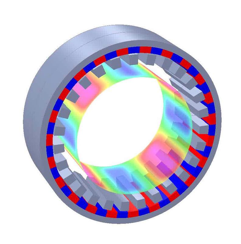 Fig 1: Arrangement of magnets and steel poles in a magnetic gear
Latimer said: “Because we’re creating harmonics, it’s quite difficult to actually predict how that works, and that’s where some of our intellectual property is. So we know that certain numbers of pole ratios work well and some don’t.”
The result is a gear that has a number of advantages over its mechanical equivalents. They are very efficient, reliable, and have no touching parts and so wear is limited, maintenance reduced and lubrication unnecessary.
There are also disadvantages. A magnet will demagnetise if it is subjected to excessive heat, so there are limits to the working environment, albeit quite extreme limits – depending on the type of magnet, they will recover their magnetism as they cool after reaching temperatures of up to about 200°C. However, if heated beyond that they will permanently be affected. High speeds are also a potential problem. Latimer explained: “You’ve got some quite chunky magnets and they want to fly off. So you start putting composite tubes around the magnets just to hold them on. And as you put the composite in place that increases the air gap which means you need bigger magnets to create the flux, which means you need more carbon fibre wrap and the technology runs away from you.”
The other main issue is that if the rotor is overloaded it will simply slip, so the magnets need to be strong enough to cope with maximum torque. If peak operation is much greater than the ordinary operating modes, then excessively large magnets need to be used to avoid slipping. This slipping can be an advantage however, as it effectively acts as overload protection.
One such example of this is with Zilift’s ‘artificial lift’ products. When an oil reservoir starts becoming depleted, it loses the pressure that initially squeezes it through the well and up to the surface. When it reaches this stage then productivity can be enhanced by an artificial lift – a pump.
Traditionally such pumping used a ‘nodding donkey’ at the wellhead to drive a reciprocating pump at the bottom of the well. This was fine in the days when wells were, relatively speaking, short and straight. Nowadays wells can be several kilometres in depth and change direction – there is far more likelihood of wear from the push rod between the nodding donkey and the pump.
Zilift puts the whole pump assembly on a cable so it can sit at the foot of the well (or any other optimal point) and be driven electrically. “They are now using the three main benefits of the magnetic gear,” claimed Latimer. “The first thing is it’s more efficient. The second thing is, it doesn’t wear out. So because there’s nothing to wear, you can keep it down there for a lot longer, because there’s no maintenance required.
“The final thing is what you’re actually pumping down there is not just oil. It’s oil, water, sand, all sorts of stuff. So, what typically happens when a chunk of sand hits the pump is the pump will tend to seize up. In a normal system with a mechanical gear that will then probably strip the gear teeth so you’re going to have to take the thing out, repair it, and put it back in. What happens with our magnetic gear is it just slips. They then detect that it’s slipped, and can stop it, reverse it and clear the blockage. Typically we’re seeing down well times that are maybe six times the life of an equivalent technology, and taking it out of the well is both expensive and also of course you lose production time.”
Zilift claims optimal pump placement in horizontal heavy oil will result in an average 60% increase in production.
The key enabling technology has been the emergence of rare earth magnets that combine magnetic strength in a small package. But, another factor that has allowed a small company like Magnomatics to develop is the use of the simulation software – in this case the Opera FEA simulation software.
“We can use our parametric design programs and design a hundred gears and then in a virtual world we can evaluate whether they are any good or not - we don’t have to make them. And you couldn’t do that 20 years ago.”
Magnetic motoring Magnomatics have taken their technology in two directions. One is the pseudo direct drive, described in the main article, which will find its applications across many sectors. The other technology goes by the name of MAGSPLIT and it is specifically aimed at hybrid vehicles. The MAGSPLIT transfers power from the engine to the wheels in a way that allows it freedom to operate at optimum engine speed and torque, but also employs high-efficiency mechanical power. The MAGSPLIT has two rotors known as the magnet rotor and the pole piece rotor, forming the basis of a magnetic gear with a fixed ratio of torque. The outer part of the MAGSPLIT is a stator – the stationary part of a conventional electric machine. Electric current flowing through the windings of this stator drives a magnetic field. The speed ratio of the pole piece and magnet rotors can be modified by rotating this magnetic field, which is achieved by controlling the current through each of the three phases. The mechanical power of the two rotors will then no longer be equal; the stator converts this difference to electrical power, which can flow into or out of the MAGSPLIT. When the stator holds the magnetic field stationary the two rotors behave like a conventional gear with the MAGSPLIT intrinsic ratio. The consequence, claims Magnomatics, are improved drive cycle fuel economy and emissions that are 5% better than a mechanical power split; 17% better than parallel hybrid; and 32% better than a conventional gearbox. |

