Robotic tendril gets into tight spaces
Tom Shelley reports on an ingenious technology developed by NASA.

A robotic 'Tendril' has been devised that can insert itself into the tightest places. Invented for use in space, its constructional basis is simple enough to make it attractive for a multitude of other uses, including keyhole surgery, inspection and maintenance tasks inside hard-to-access machines.
Its inventor is a team of engineers at the Johnson Space Center in Houston, Texas and its original purpose was to be able to inspect deep into crevices, under thermal blankets, or down damage holes caused by MicroMeteoroid Orbital Debris or other impacts on space vehicles. For such purposes, it needed to be at least 100 times as long as it was wide and able to support a small video camera on its tip.
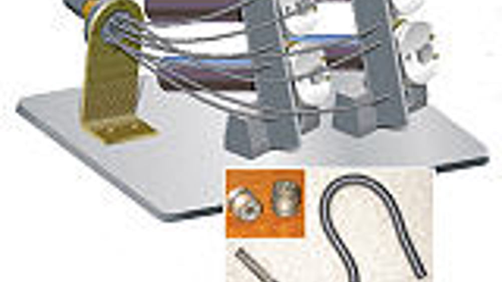
Its basic construction is as a series of extension and compression springs joined by threaded links. The extension spring sections provide passive bending along the majority of the Tendril's length, while the compression springs allow active bending under the action of antagonistic tendons. These run along the length of the Tendril and terminate at one end within the Tendril and at the other end on pulleys. When a particular pulley rotates, one tendon in a pair is retracted and the other is allowed to extend. This causes a compressive force on one side of one of the compression springs, making it bend. Each of the Tendril's two bending sections is equipped with two pairs of tendons, routed perpendicular to each other. The current design has two 8cm bending sections actuated by 0.25mm diameter 'Spectra' gel spun polymer tendons.
The tendons that control the distal section (that furthest from the pulleys) are offset 45º from those that control the proximal section (that nearest to the pulleys). In addition to all eight of the actuation tendons passing through the threaded links, each link has a central bore for power and video connections to the CCD camera mounted on the Tendril's tip.
The actuation assembly consists of the four pulleys and brushless DC motors to drive the eight internal tendons, as well as a routing structure to direct the tendons into the Tendril. The tendons pass through PTFE tubes both in the routing structure and in the Tendril itself in order to reduce friction. The 2.5cm diameter pulleys are sized in such a way that their full range of motion allows for more than 90° movement in both pitch and yaw at each bending section. The actuators produce 0.4Nm torque, which is more than sufficient to overcome the effects of gravity when the Tendril is hanging vertically.
The body housing accommodates the withdrawn Tendril on a reel, as well as a body rotation actuator. A spiral groove is formed into the circumference of the reel to guide the Tendril during extension and retraction and to confine it to a single layer during multiple revolutions of the wheel. The reel is driven by another brushless DC motor that produces 1.7Nm of continuous torque at 120 rpm, which is more than sufficient to drive the Tendril at 5 cm/s.
The body rotation creates a roll axis for the Tendril when the tip is straight and gives the Tendril an auxiliary means of panning a full 360º when it is bending. The actuator also uses a brushless DC motor, producing 2.5Nm of continuous torque at 91 rpm and a holding torque of 24.5Nm. An absolute position measuring device with an inductive sensor was custom designed for the application. This both relates the rotational motion of the reel to the linear motion of the Tendril and acts as a hard stop to prevent it either over extending or over retracting.
Full details including engineering drawings may be downloaded from the NASA Tech Briefs website http://www.techbriefs.com. Anyone interested in licensing the technology or in further collaborative developments should contact the Johnson Space Center - jsc-techtran@mail.nasa.gov.


