An acronym that you are no doubt going to be hearing a lot more of is DFAM, design for additive manufacture. Like any manufacturing process, additive manufacturing (AM) has all kinds of constraints and best practice that should be followed to get quality, as designed, cost effective parts.
One of the most obvious restrictions is geometry. While this might induce a gasp from many readers that think the process can make anything, do not despair. You probably can make it, but you need to design for this machine and process, which often requires a bit of lateral thinking.
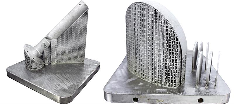
The first thing to note is that 3D printers don’t really do overhangs well. It makes sense that you always need material to upon and this means that parts with an inverse incline or overhang need adequate support structures designed in place to make them printable.
“Support structures are essential,” said Eric Mutchler, a laser sintering product manager with 3D print bureau service, Stratasys Direct. “Where larger supports are needed, and to save material, these can be made from a lattice structure. But there are limitations.”
The good news is, there are numerous software packages that automate the production of support structures.
Another adjustment – particularly with metals – is coping with the internal stress that is induced layer by layer in to the part. As each layer is applied, the rapid heating and cooling of powder means the layer want to curl upwards. To minimise this effect, orientating the part so it maximises the cross-section of each layer to help with heat dissipation, and also this helps minimise overhangs. Stress relief cycling in a furnace can also help minimise this effect.
“Geometry evaluation and print orientation is the first thing we do before we print something for a client,” said Mutchler. “We identify risk by looking at overhangs, small features or trapped volumes.
“Once we start diagnosing some of the problems we’ll either build it with accepted risk and let the risk be known, or redesign the part. We might even build a sample of what we think might be a trouble area.”
This is all not to say, ‘stay away from complex geometry’. However, like composites, the challenge of AM is designing parts for the process, and that often means consolidating multiple components together. Like composite ‘black metal’ parts, AM can have similar pitfalls and in most cases needs designers to understand the process and use a bottom-up approach to design, rather produce parts designed for traditional manufacturing, be disappointed by the results and then wonder what all the fuss is about.
The right angles
The angles of parts on the XY plane are critical when 3D printing, especially parts made in metal. If the angle is taken from the horizontal build plate, then a good rule of thumb is, anything between 0 and 30° is going to require supports. From 30° upwards, aluminium can be built without supports, as can most plastics, but most other materials will produce a print anomaly known as ‘burn’. This is where material being laid down doesn’t have material below it to build upon. While there are extreme cases where parts can’t be built because of burn, the most common outcome is that it increases surface roughness or leads to some kind of degradation in the part’s properties. If burn is likely, it is advisable to add extra material that can be removed later.
Difficulty also arises when producing hollow parts such as pipes or channels within a part that might transfer air or a fluid. Intricate and innovate heat exchangers are a common area of interest for metal based AM, but if the pipes require support structures, they must be able to be removed.
Similarly, AM doesn’t really print holes particularly well, and these are best designed smaller, essentially as a pilot hole, that can be drilled out later in post processing.
“I hate having to say this,” said Mutchler, “but this process is very geometry dependant.”
As AM technology move beyond being prototyping tools do not underestimate the need to design specifically for this process. In addition, as AM makes the transition in to mainstream manufacturing toolbox, do not be surprised by the amount of post processing that maybe needed.
“If you look at the entire process to get to the finished part, AM is only one step,” said Mutcher. “All the other steps are conventional ones. You still need to have milling, wire EDM, lathe operations, and anything else you’d expect to use when building a high end part.”
Top tips when designing for additive manufacturing
|
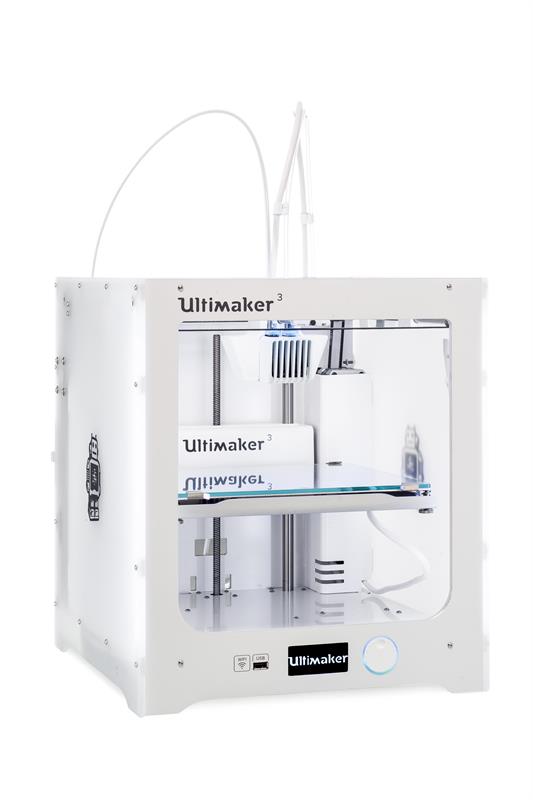
Ultimaker 3 – professional printing Ultimaker has released its next generation 3D printer, the Ultimaker 3. The device is priced at $3495 and features print cores with a customised internal geometry which allows it to extrude two materials at once. The printer uses PVA as its soluble support material, which is also environmentally friendly and can be extruded along with nylon, PLA and ABS. It provides the capability to print complex geometries using industrial-grade materials right from the desktop. It comes with fully integrated hardware, software and materials configuration to ensure both efficient workflow and precision print results. Smart material detection through NFC (near field communication) technology on the spool racks, as well as active bed levelling, help to tune Ultimaker 3 to the best possible settings for specific materials and corrects level errors. The printer has Wi-Fi and Ethernet support as well as a USB port and also has an on-board camera allowing remote viewing from your workstation to help speed productivity. Croft added: “With its unlimited geometry, unique print core, enhanced automation and advanced connectivity, Ultimaker 3 is going to make even more possibilities a reality within the professional sector.” |