
Everything needs to be ‘smart’ nowadays. Clever electronic systems are being increasingly integrated in to all sorts of products to harvest data and transmit it. It is a trend that is set to exponentially increase.
This rise of the machines – often referred to as the Internet of Things – means more wires, more antennas, and more electromagnetic compatibility issues, a side effect that is seldom discussed by the mainstream.
Electromagnetism (EM) is one of four fundamental interactions found in nature, and its management is as much about getting it to do what you want, as it about mitigating and managing unwanted side effects.
This growing need has been reflected in the fact that simulation software and product design consultant company Altair acquired EM Software and Systems last year to enable FEKO, its comprehensive electromagnetic simulation software tool, to be added to its extensive Altair HyperWorks suite of multi-physical simulation solvers.
Vice president of electromagnetic solutions at Altair, Dr Ulrich Jakobus, explained: “The cross-sector, cross-industry increase in electro-dynamic systems means we need to better understand and engineer systems that produce electromagnetic radiation so we can maximise functionality and minimise any undesirable effects.”
FEKO is a state of the art solver specifically configured to assess a broad spectrum of high frequencies. It uses various different frequency time domain techniques and hybrid solvers to analyse a whole spectrum of electromagnetic problems.
The industry sectors are diverse and cover everything from automotive to aerospace, communications to medical application. The key applications are antenna problems, from their design and performance to their placement on a structure.
Like much of the Hyperworks portfolio, FEKO can be used to tackle problems on products large and small, from mobile phones to warships. However, FEKO is perhaps most prolific in its use to design and place antenna on structures, assess their interaction with surrounding wiring and materials, as well as understand any affect from the surrounding environment and on personal.
Antenna placement
Design engineers are notoriously preoccupied with packaging, neatly placing as many components and systems in as small an area as possible. However, this often creates problems and headaches when it comes to electromagnetic interference.
“Typically the design engineers tell you, ‘this is the space you have to put an antenna’,” said Dr Marcus Schick, director of electromagnetic solutions at Altair. “Then you find the EM engineer has a problem: how to get good reception with the given parameters that you have?”
However, awareness of the need to improve dialogue between designers and EM engineers is improving, especially given the trend of integrated antennas. For example, an average mobile phone can have half a dozen antennas and cars more than 20, yet it is often difficult to even find a single one.
Placement, interaction, performance and interference all need to be thoroughly understood and assessed if functionality is not to be compromised. Getting it wrong can be embarrassing, as was the case for Apple several years ago when the iPhone 4 suffered reception problems as a result of bridging the antenna with the metal shrouding on the phones edges. When a user’s fingers touched the metal shrouding, the signal was considerably weakened causing calls to be dropped.
“We want to analyse what the antenna is doing, but also what will happen when you put it on a structure,” said Debbie Fellows an EM application engineer at Altair. “What are the interactions going to be? Will that affect performance? And alongside that, you always have unwanted performance, so it helps to really understand electromagnetic compatibility issues.”
The automotive industry is a case in point. Over the last five years engineers have trended toward using the wires used to heat the rear window as antennas, up to seven on some models, receiving different signals at different frequencies. In addition cars now have more sensors and wiring than ever before, all emitting electromagnetic radiation that has the potential to cause problems if not properly managed.
The biggest megatrend for the industry, however, is electrification. This maybe hybrid cars or all electric, but both create substantial new electromagnetic signatures. Electromagnetic compatibility (EMC) can be used to improve the design of the electric systems and equipment, optimise how they interact with the rest of the structure and materials, and reduce the overall cost of the project.
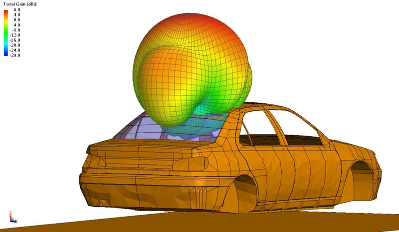
Dr Salah Benhassine, a specialist in EMC numerical simulation at PSA Peugeot Citroen Automobiles, has been tasked to look specifically at this problem. He explained: “We model hybrid cars and their EMC emission. We have to model the whole structure of the car, the metallic pieces, and also we have to take in to account the antenna on the roof or integrated into the windscreen. Then we have to describe the hybrid system that takes in to account cable harnesses... and the effect on people.
“We might find radiation from equipment that could affect the antenna, especially when you have higher power.
|
 Engineers have trended toward using the wires to heat the rear windows as antennas, up to seven on some models, receiving different signals at different frequencies.
To shield or not to shield?
In the Peugeot systems given as an example, the front wheels use electric motors and inverter. In the rear of the car there is a 48v battery, a DC/DC converter, and also some grounding on the chassis.
It was clear there would be some issues and so analysis was run to see if cables needed to be shielded or unshielded. While shielded cables would reduce any EMC, for every car this would add both cost and weight. The alternative solution was to use filtering instead.
“We had to model the whole vehicle and whole cable harness, and then look at the distinction between shielded and non-shielded,” said Dr Benhassine. “We wanted to see what happens if we group the cables together or if we separate them. We introduced some filtering and we could see the behaviour that had on the antenna.
“It shows we could reduce the levels if we used only a filter on the 12v cable instead of putting shielding on the whole cable, probably 5 or 6m. This simple filter reduced noise by 40dB across the whole system. Using EM simulation, we can highlight the worst or best configuration, optimise the routing of the cables, optimise the grounding, and also give good filtering according to the frequency.”
Cable coupling can also create undesirable electromagnetic effects. In general, cable harnesses are often placed in multiple bundles that get threaded through in all kinds of arbitrary places, as they run through vehicles. This is often without huge thought about how they are implemented.
FEKO features a cable analysis tool that assesses the electrical fields coming in to cables, what happens with the energy along them, and ultimately the affect this has on other electrical sensors and systems.
“Cable coupling is important when it comes to electromagnetic compatibility,” concludes Dr Jakobus. “But we are interested in using it with other solvers in Altair in the multi-physical analysis such as thermal or vibration analysis. Take a car, for example, that has a radar on the bumper to measure the distance to the car in front as part of an adaptive cruise control system. We need to know how that interacts with the vibration from the road. We don’t want a pot hole to make the radar give false or inaccurate readings. So we need to assess this interaction, the multi-domain, multi-physical, system.”
CFD with automated calibration Mentor Graphics has announced the latest version of its FloTHERM computational fluid dynamics software solution. FloTHERM was developed to identify potential thermal issues early in the design process to avoid expensive late stage re-design and warranty costs arising from thermal failures in the field. The latest version is claimed to deliver an automated method to calibrate simulation models to match transient thermal measurements recorded with the Mentor Graphics’ T3Ster hardware. As a result, FloTHERM can help maximise simulation data accuracy and provide additional insight into product reliability for the automotive, aerospace and electronics products industries. T3Ster is an advanced thermal tester for thermal characterisation of IC packages, LEDs and systems. The test system is said to deliver accurate, real-time measurements of heating and cooling transients based on its implementation of the JEDEC static test method. |


