
Wind turbines stand around 130 metres high, weigh dozens of tonnes and have average rotor diameters of 110m. If such equipment fails, cranes and other machines are typically unavailable at short notice and offshore wind farms are not exactly easy to access at any time of day or night, so costs are high.
Due to wear and the complexity of assets in addition to environmental influences, there are several possible problems such as shaft issues, gear faults, gear wheel wear, material fatigue, imbalance, temperature differences, lubrication faults and bearing clearances, which not only impede smooth operation but might also involve other subsequent or secondary damage.
Proactive monitoring based on precision sensor technology is already used in the production process of wind turbines and continues in test rigs and in the real-time monitoring of turbines during operation. Worn parts or deviations in production can now be recognised before catastrophic damage occurs.
Not only can current asset conditions be documented, but trends and changes in measurement data can be analysed and evaluated. Maintenance becomes predictable and sudden failure or downtime of these large plants is reduced to a minimum.
“Innovative sensor solutions are now available that enable reliable measurements and targeted evaluation of critical data,” explains Chris Jones, managing director of Micro-Epsilon UK. “This sensor technology helps customers by preventing repairs, reducing failures, reducing costs and helping to predict maintenance cycles. Compared to manual inspection where differences can depend on a person’s tiredness and mood, sensors can provide high precision, reliable, repeatable measurement results 365 days per year.”
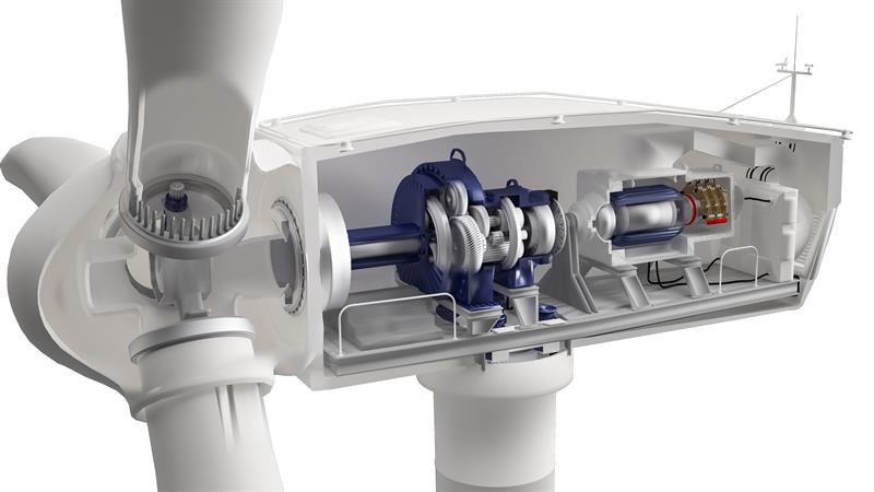
Offset measurement of the coupling ring
Above 100m high loads act on the rotor blades, housing and tower, caused by wind. The gearbox and generator have an elastic bearing. This is why couplings in wind turbines must balance the relative movement of the gearbox and generator. When measuring the offset of the coupling ring, non-contact eddy current displacement sensors can be used to determine the distance, while measuring onto the metallic coupling ring. This leads to the determination of the load profile.
Monitoring the measured values is required in order to avoid unnecessary wear of couplings, bearings and shaft seals or, in extreme cases, serious damage to the wind turbine. Eddy current sensors allow measurements to be carried out in different directions – in the axial, radial and tangential axes. Some suppliers offer temperature-compensated versions that provide high measurement stability, even in strongly fluctuating ambient temperatures. The sensors are factory-calibrated for ferromagnetic and non-ferromagnetic materials, which eliminates the need for field calibration of the sensor.
Compared to inductive switches and sensors, eddy current sensors provide a higher bandwidth and so are suitable for precise detection of high-speed movements.
Hydrostatic bearings are used in wind turbines. The task is to monitor the gap size between the bearing surface and the shaft.
In the lubricating gap is an oil film, which prevents direct contact between the bearing surface and the shaft. In the case of a malfunction in the hydraulics, the oil pressure can rise, and in extreme cases, the gap will close. This would lead to damage of the bearing and in turn to a possible turbine failure.
Jones says: “Our sensor is mounted horizontally to the bearing shoe. It measures through the oil film and the plant bearing directly onto the shaft. Here, non-contact eddy current displacement sensors can be used, which are robust, compact and have an integral controller.”
As well as offering resistance to high pressures, lubricants and extreme temperatures, these sensors are also said to enable rapid commissioning and can be retrofitted to existing wind turbines.
With very large generators and electric motors, it’s important to determine the radial run out of the rotor inside the motor compared to the stator.
Due to imbalances during operation, which could be due to wear caused by extreme wind and weather conditions, the rotor might touch the stator, which could lead to catastrophic failure. Therefore, non-contact optical and capacitive sensors are used to measure the distance between the stator and rotor and to monitor the rotor gap whilst the motor is running.
During air gap monitoring in a wind turbine generator, the average temperature is 120°C. Some capacitive sensors are specially adapted to measurements in a generator, they are resistant to vibration and are protected by a special housing. Their triaxial design enables flush installation into electrically conductive materials as the guard ring electrode and grounding are also located on the front edge of the sensor alongside the measurement electrode
The gearbox temperature is measured during operation. Heating up of gearbox components may indicate a potential problem with a component. Subsequent remedial action can be started, or maintenance planned.
To control air supply, the air flaps automatically open and close depending on the temperature. Draw-wire displacement sensors can monitor the position of the open-air flap.
In order to monitor the supporting moments, eddy current displacement sensors measure the distance between the wind turbine nacelle and the tower, which enables early recognition of any fluctuations
Non-contact laser triangulation sensors are ideal for measuring the distance between the tower and the foundation. High measuring rates enable the sensors to detect any changes reliably. Depending on the number of sensors installed, detailed evaluations about the vibration behaviour of the mast can be determined.
Test rigs have been developed for load tests on wind turbine rotor blades, which simulate the real loads caused by high winds and extreme weather conditions. The tip of the rotor blade can be distorted by up to 10m due to mechanical loads.
Draw-wire sensors are mounted on these test rigs for measuring this distortion. Two sensors per traction point measure the deflection and torsion of the rotor blade. The draw-wire sensors operate with measuring ranges between 3m and 10m. The digital signal output is provided for further simulation and analyses.


