
There are many engineering challenges involved in designing and building a huge functional wing with numerous moving parts, whilst ensuring sufficient strength and minimal weight. The R1 is a state-of-the-art catamaran that lifts out of the water on a pair of hydrofoils. This type of foiling design has allowed the yachts to reach speeds of around 60mph.
On the R1, the control surfaces are driven by hydraulic actuators. Hydraulic pressure is provided by ‘grinders’, crew members who turn specialised hand-cranks. When Land Rover BAR realised that control precision could be compromised by the somewhat convoluted load-path between actuator and control surface, they looked to measure the control surface movements directly and contacted Renishaw’s Technical Innovation Group for help.
Technical leader Dr Finlay Evans and his team designed a special magnetic position sensor (encoder) for the wing flap control surfaces, which achieved better direct feedback. This allows the helmsman and crew to race the boat with more precision whilst enabling the capture of high-quality performance data during development and training.
“The encoders are on the main wing: one at the top, two on the main body of the wing and one at the bottom,” says Dr Evans. “A fifth encoder is mounted on the hull at the bottom of the mast. The wing encoders measure the wing flap twist from top to bottom and the one on the mast determines the angle-of-attack of the whole wing assembly. In addition to that, there are two in the hull for measuring the positions of the port and starboard rudders.”
Dr Evans adds that by using encoders directly on the control surface, or as near as possible, you get a more accurate reading of the angular position of the control surface. The fact that they are magnetic rather than optical came down to the harsh environment they would be working in.
“Consider the implications of high speed winds and salt spray going everywhere,” Dr Evans says. “Open optical encoders would be a real challenge because you must keep the optical path clear. Magnetic encoders can be fully sealed giving much greater contamination resistance, which is essential for this application.”
 In this case, a magnet is attached to the back of a Hall sensor array and is used in conjunction with a ferromagnetic scale, which has a series of lines (grooves) etched into it. The grooves in the scale surface produce changes to the local magnetic field, so when the sensor is moved over the scale, a moving magnetic pattern is detected by the Hall sensors, which is then converted into a position measurement. Because the pattern of the scale grooves is non-repeating, the absolute position can be determined anywhere on the scale. The sensor head assembly is completely encapsulated to protect its sensitive microelectronics from the elements. The outer polymer layer also gives a sacrificial surface where the scale makes full contact, which ensures correct ride height. Magnetic encoders are also unaffected by encapsulation.
“The design process was based primarily around the requirements of the encoder,” Dr Evans says. “A small amount of mass at the top of the wing makes a big difference to the performance and stability of the overall boat.”
He adds that space was also a prime consideration – the space restriction came about because the actuation surfaces are in small spaces with small clearances.
“Our traditional encoders are designed to run with moderately small ride-heights on good linear or rotary axes,” Dr Evans continues. “Here we have a tight requirement in terms of measurement accuracy along an arc that is not just moving axially, but also twisting as it rotates. We had to come up with a way of maintaining the measurement accuracy throughout the out-of-plane twisting and pitching.
“Magnetic sensors are arguably the best technology to use in terms of contamination resistance, although ride height tolerance is very tight compared with typical bearing movements in a boat and wing of this size.”
Understanding Land Rover BAR’s requirements was an important aspect, but given the time restriction, Renishaw had to select technology from pre-existing commercial encoders. Space and geometry requirements in the wing were significant factors in determining the design. Dr Evans’ team started with a module that exists for a linear encoder for use on a precision plated shaft with carefully shaped grooves embedded under the surface. They had to effectively unwrap that code and embed it into a flat surface with differently shaped grooves along an arc using a new process and hope that the resulting flat arc equivalent scale would work first time.
“We took the pre-existing LinACE module from our RLS associate company, and repackaged it into a waterproof encapsulation – which we hadn’t done before – to allow it to survive the operating environment,” says Dr Evans. “This also provided an encoder body that was small enough to operate within the tight dimensional constraints of the highly stressed wing ribs. We also had to come up with a solution that allowed the scale part to twist and move but without inducing significant errors when the sensor moved.”
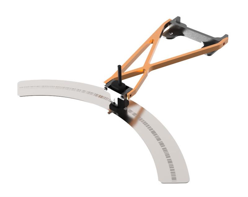
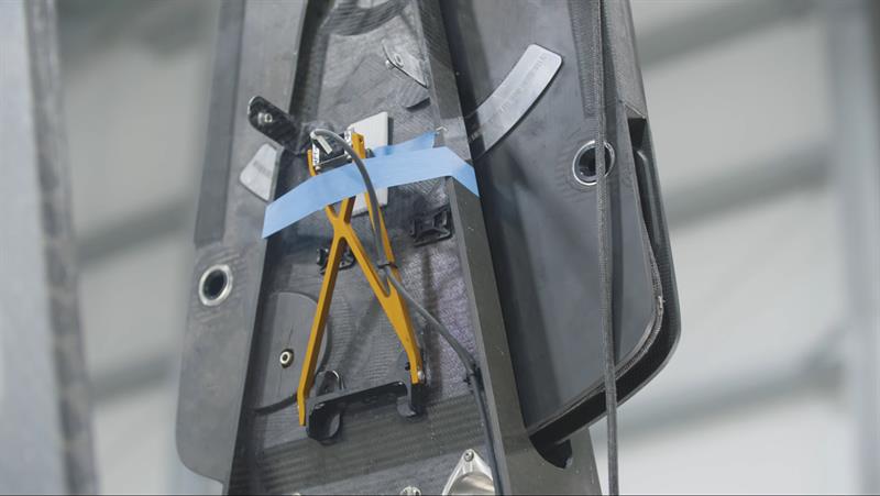
To address this, Dr Evans’ team came up with a gimbal arrangement for the sensor whereby the partial-arc scale twists out of its plane of rotation without inducing inaccuracy. A special aluminium wishbone and yoke assembly was designed to hold the readhead precisely while allowing for pitch and roll. The wishbone is attached to the wing’s static structure. This whole encoder assembly is said to give a more accurate reading of the position of each flap than inferring from actuator movements.
“All these design features together were crucial to the success of the overall encoder system,” Dr Evans concludes. “These building blocks were all separate mini-projects in their own right and ensuring each was successful first time was the biggest challenge.
“Finding a way to bring all these elements together successfully within the short timescales involved a rapid response from both our RLS colleagues in Slovenia and our own in-house manufacturing facilities. I’m proud of what we achieved.”


