
Advances in technology make modern high-performance machines possible due to:
- Sophisticated sensors
- Computing power and algorithms that enable real-time decisions and actions
- Motors that have the speed, accuracy, and mechanical power to accomplish increasingly complex tasks.
Each plays a vital role in robot design, because technological advances and the synergy among them builds rapidly on itself.
Traditionally, managing the motor has been a challenge for electronic engineers, since many issues are different from those in the more-familiar electronics. Fortunately, technology has made these issues easier to deal with, while also enabling impressive performance. For instance, Texas Instruments' DRV8816 dual half-bridge motor driver has integrated internal protection functions and a low-power sleep mode to achieve very-low quiescent current draw. Highly integrated controllers and drivers point to the level of flexibility and integration that electronics and motors have achieved.
Choosing a Motor
There are three primary parameters that designers consider when selecting a specific motor type and model:
- The minimum and maximum motor speed (and associated acceleration);
- The maximum torque the motor can deliver, and the torque vs. speed curve;
- The precision and repeatability of the motor's operation (without using a sensor and closed-loop control).
Of course, there are many other performance factors involved in motor selection, plus size, weight, and cost factors. For nearly all small-to-moderate-sized robotic actuators, the most common choices for powering the actuator are the brushed DC, brushless DC (BLDC), and stepper motors. (However, there are some cases in which pneumatics and hydraulics are the best choice.)
Brushed motors, the oldest DC-motor technology, are the simplest and least-expensive choice. The rotation of the motor's rotor switches (commutates) the field of the windings around the rotor via current-carrying brushes that make contact with the rotor. The motor speed is a function of the applied voltage, so the drive requirements are minimal, but managing the torque is difficult. They also have reliability issues due to brush wear-out, may need maintenance for cleaning, and are a source of electrical noise (EMI). For these reasons, brushed-DC motors are the least-attractive choice for robotics in most cases.
Brushless DC motors (Figure 2) came about in the 1960s and are an improvement over brushed motors due to strong, small, low-cost permanent magnets, and small, efficient electronic switches (usually MOSFETs) to toggle the current flow to the windings. "Electronic commutation" replaces the need for brushes that actually touch the motor, so that a magnetic field is switched on and off. Thus, the relationship between a magnetic field and electrical energy flow is exploited. The motor speed is controlled by changing how fast the MOSFETs are switched on and off. In addition, the motor controller has tighter control over motor performance than a brushed motor.
|
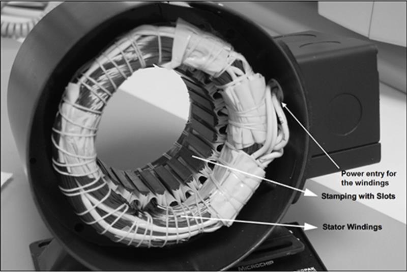 Figure 2: In the brushless motor, the coil currents are electronically switched in the stator windings while their magnetic field interacts with permanent magnets on a rotor. In this image, the missing rotor belongs in the centre. (Source: Microchip AN885)
But even better control is possible with these motors as advanced algorithms such as PID (proportional-integral-derivative) or FOC (field-oriented control, sometimes called vector control) can be embedded in the motor controller. This matches the desired motor operation to the reality of the load and load changes, providing enhanced, more accurate performance. For example, motor control algorithms/programs can account for the rotor's inertia, and adapt the motor drive accordingly, reducing errors due to mechanical issues. Using tailored algorithms enables more precise control of acceleration and torque.
Compared to brushed motors, brushless motors (BLDC) need more complicated control electronics but can deliver far better performance. BLDC motors usually require position feedback via Hall Effect sensors, optical encoders, or via sensing of back-EMF.
One specific type of BLDC motor used often in robotics is the stepper motor (Figure 3), which uses switched electromagnets arranged around a central core that is arrayed with a ring of permanent magnets. Steppers do not "rotate" in the normal sense; instead, the shaft is directed to move in finite, step-by-step increments (steps) and so can be directed to turn just a fraction of a complete revolution as well as to rotate continuously. Steppers have very repeatable motion control; the stepper can return to a position exactly where it was before, if directed to do so.
"Step" angles are typically as small as 1.8°, which yields about 200 steps of movement over 360° (one revolution). Step angles of 30° over 360° of movement yield 12 steps per revolution (12 X 30 = 360). The step angle or the number of steps per revolution depends on the number of permanent magnets the motor has, but higher and lower values are available.
|
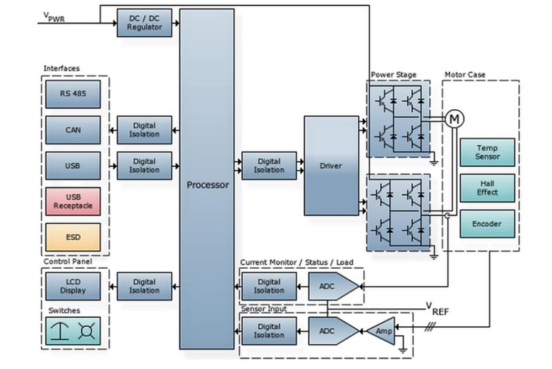 Figure 3: Block diagram of a stepper motor with all the components. MOSFETS are located in the power stage. Source: Mouser Electronics.
With stepper motors, if power is held "on" but no stepping is directed, they hold their position. Steppers can provide high torque at low rpm. The most direct way to cause the stepper to move is to turn the electromagnets on or off in sequence, but this can cause chattering or vibration.
There is application overlap between BLDC and stepper motors. Steppers are better suited for applications that require precise back-and-forth motion, such as pick and place, rather than continuous rotation for long periods, and for smaller applications that don't require the motor to provide high torque or speed. Also, steppers are not as energy-efficient as brushless-DC motors.
There are many other motor options, as well. The family genealogy tree for motors is long and complex, with many siblings and cousins. For example, the permanent-magnet synchronous motor (PMSM) is a combination of a brushless-DC motor (with respect to the rotor) and an AC-induction motor (with respect to stator structure). It features high-efficiency, relatively high power in a small package, a high torque/weight ratio, fast-response times, and is fairly easy to control, but can be costly.
Control Requires Finesse
A robotics motion system is more than just a motor; it consists of three major functional blocks:
- The real-time controller, which can be implemented in one of three ways:
- A general-purpose, computationally fast processor running motion-control firmware
- A DSP-oriented FPGA programmed for the control application
- A dedicated controller IC with hard-wired, embedded algorithms.
- One or more driver stages in series, to take the low-level signals from the controller output and interface them to the higher-voltage/current needs of the electronic switches.
- The MOSFETs (or other switching element such as IGBT or bipolar transistor), which actually control the flow of current to the motor windings.
Choosing a MOSEFT for a motor requires knowing the current and voltage demands of the motor and its windings. Then the MOSFET, to be turned on and off, needs a driver, which is in turn determined by the MOSFET's rating. Indeed, a series of step-up drivers may be needed depending on the MOSFET size.
Questions to Ask in Choosing a Controller
Choosing the type of control to use for all of this is a strategic choice that should be made before selecting a specific vendor or model. This is because there are many trade-offs when deciding to use a general-purpose processor that is well-suited for motor control, a computation-friendly FPGA, or a dedicated control IC (the latter is most often from a specialized motion-control vendor). Some of the points designers must consider include:
- What level of control algorithm sophistication and complexity do you need, and how much I/O?
- Who provides the control algorithms and code: the IC vendor, a third party partnering with them, or an unrelated third party? How are they verified and tested for your motor and application?
- How much user-programmability do you need? Even dedicated, non-programmable controllers allow users to select algorithm type, closed-loop control mode (position, velocity, acceleration) and set operating parameters.
- Do the motor and application have unique attributes? If so, a programmable IC might be better. What if there are constant requests to modify the algorithm? In this case, a dedicated IC with hard-wired embedded algorithms may be better than a fully programmable IC.
- Does the controller have to support multiple types of motors? Even if just one type, is it one motor size of that type, or a range of sizes?
- To what level does the vendor provide technical support? What is their actual, hands-on motor experience? Do they provide detailed reference designs that have been built and tested, including the interface between the control IC and MOSFET drivers?
- Are there regulatory issues to be aware of, such as mandated efficiency (many motor applications must now meet various "green" standards)? If so, does the vendor understand and meet them, in their components and algorithms?
Development Kits Show Controller and Interface Capabilities
For many engineers, pulling all the parts together - the controller with embedded or separate algorithms, the drivers, and the MOSFETs - is a multidisciplinary task, and one for which they don't want to "reinvent the wheel." For this reason, many vendors provide evaluation boards or complete kits with controller, sample algorithms, drivers, and MOSFETs. One example is the Freescale MTRCKTSPNZVM128 3-Phase Sensorless PMSM Kit to drive 3-phase BLDC or PMSM motors using sensorless motor control techniques. This rather sophisticated kit is designed to enable rapid prototyping and evaluation via back-EMF sensing using the microcontroller's integrated ADC modules. Alternatively, this same kit (featuring the MC9S12ZVML12 microcontroller) can be configured as sensor-based for evaluation of operation using Hall sensors or resolvers.
Robotics has an exciting future ahead as advances in technology, including precise actuation via improved motor controls and sensing creates new opportunity. Sensing, control, and motors are key areas where innovation will continue to shape how robots evolve as innovation in technology continues to unfold.


